

Software is no longer a bit-part contributor to electro-mechanical systems but is now the underlying technology providing functional safety for products in many market segments. The requirement for software functional safety has therefore become a critical topic in industrial automation, transportation, nuclear energy generation and similar sectors. IEC 61508:2010 “Functional safety of electrical/electronic/programmable electronic safety-related systems” is an international standard published by the International Electrotechnical Commission. Although IEC 61508 is often applied directly in the development of safety critical systems, its generic nature also makes it an ideal “blank canvas” for the derivation of industry and sector specific standards.
Functional safety is concerned with the management of the level of risk in a piece of equipment or a system.
Functional safety development processes aim to identify potentially harmful conditions and to identify corrective actions to avoid or reduce the impact of an incident such that the response is proportionate to the risk.
In practice, functional safety relies on active systems that can respond to a potentially dangerous situation. Examples include the initiation of sprinkler systems in response to a smoke detector being triggered, or the automatic deactivation of a heating element when a predefined temperature has been reached.
IEC 61508 is applicable to both such situations because both rely on electrical/electronic/programmable electronic safety-related systems.
The international standard IEC 61508 consists of seven parts:
The primary part of interest from the perspective of a software developer is IEC 61508‑3:2010 “Functional safety of electrical/electronic/programmable electronic safety-related systems – Part 3: Software requirements”.
However, as the above outline of the parts suggests, all parts are relevant to some extent.
Embedded software developers will be primarily concerned with part 3 of IEC 61508:2010, “Software Requirements”. However, the level of effort required to complete each objective in this international standard is dependent on the Safety Integrity Level (or “SIL” – not “SIL level”) of the safety functions implemented by the system. The derivation of the SIL is covered in more detail in part 5 of the standard, “Examples of methods for the determination of safety integrity levels” which explains different quantitative approaches to the derivation of SILs.
Annex A of that standard discusses the concept of “Necessary risk reduction”. Tolerable risk is dependent on such as the severity of injury, the number of people exposed to danger, and the frequency and duration of that exposure.
The standard goes on to define Safety Integrity as “… the probability of a safety-related system satisfactorily performing the required safety functions under all the stated conditions within a stated period of time”.
The SIL assigned to each safety function therefore depends the probability of failure, which can be derived in several different ways. The higher the probability of failure, the higher the SIL (from SIL1, through SIL2 and SIL3, to SIL4) and the more demanding the overheads on software development to make the risk acceptable.
The SIL safety categories are:

The full title of the standard is IEC 61508:2010 “Functional safety of electrical/electronic/programmable electronic safety-related systems”. This is a bit unwieldy, so it is often abbreviated to “Functional safety of E/E/PE safety-related systems”, or truncated further to “Functional safety of E/E/PES”.
According to IEC 61508-4 §3.6.7 and where EUC is defined as the “Equipment Under Control”, a dangerous failure is:
“a failure of an element and/or subsystem and/or system that plays a part in implementing the safety function that:
Conversely, IEC 61508-4 §3.6.8 defines a safe failure as:
“a failure of an element and/or subsystem and/or system that plays a part in implementing the safety function that:
These definitions are primarily concerned with the mechanical and electrical aspects of the EUC, rather than the EUC control system. However, in cases of failure the expected behaviour of the control system will likely vary depending on the perceived failure mode.
IEC 61511 “Functional safety – Safety instrumented systems for the process industry sector” is an example of an industry-specific standard derived from IEC 61508. At a conceptual level its life cycle processes are very similar to IEC 61508, IEC 61511, however, uses terminology and contextual examples that are directly relevant to the process industries.
The software development processes promoted by the two standards are identical, with IEC 61511 simply referencing IEC 61508.
ISO 26262 is another example of a sector-specific standard that has been derived from IEC 61508. In some respects, ISO 26262 is more prescriptive than IEC 61508 – for example, unlike the parent standard, it defines a particular Hazard and Risk Analysis (HARA) technique to be followed.
More generally, variations between the standards reflect the specific circumstances of the automotive industry. One reason is that production volumes for cars are much higher than those for most safety-critical applications, and (for example) a “proven in use” approach is more valid here.
Other variations include the use of “ASILs” (Automotive Safety Integrity Levels) which are derived differently, with ASIL being a qualitative measurement of risk.
However, both ISO/SAE 21434 and SAE J3061 present a worthy set of goals for software developers to achieve, and the lack of detail affords flexibility on how they are achieved.
ISO 13849 “Safety of machinery — Safety-related parts of control systems” is one of two standards that are harmonized to the EU’s Machinery Directive, with EN IEC 62061 “Safety of machinery, functional safety of safety-related electrical, electronic and programmable electronic control systems” covering similar ground. A third standard IEC/ISO 17305 to merge the two has been cancelled. In the meantime, ISO 13849-1 suggests that SRP/CS designed to an appropriate level in any of the ISO 13849, IEC 62061 and IEC 61508 standards can be combined.
This V-model maps the capabilities of the LDRA tool suite and complementary tools to the IEC 61508:2010 development lifecycle.

Although part 3 of the standard has the most impact on software development, IEC 61508-1 is also significant in that dictates the system-wide functional safety principles that apply to all engineering activities, including software.
It therefore impacts software development in several ways. IEC 61508-1:
The application of LDRA tools in the fulfilment of the following IEC 61508-3 objectives should be considered in the context of these overarching principles.
IEC 61508:2010 §7.2 highlights the objectives associated with the specification of software safety requirements. These include the derivation of functional safety requirements for the software safety functions, the software systematic capability, and the implementation of the required safety functions.
The V-model illustrates the need for each step in the process to be traceable to the next, as implied by the verification arrows during the lifecycle, and the validation step at its end. Bidirectional traceability is specified as an explicit objective in this international standard’s Annex A.1 table.
Bidirectional Traceability helps to ensure that all outline requirements (including functional safety requirements) have been completely addressed, that all detailed requirements can be traced to outline requirements, and in the case of software requirements that there are no surplus, spurious code.

The TBmanager component of the LDRA tool suite automatically maintains the connections between the software requirements, development, and testing artefacts and activities, ensuring that any changes in the associated documents or software code are automatically highlighted. Any consequential re-testing can then be dealt with accordingly.
This section discusses the selection of the programming language(s) to be used and the associated tool chain for the development of the code, including verification and validation tools (§7.4.4.2), static code analysers, test coverage monitors and configuration management tools.
The standard recommends that “The programming language chosen should lead to an easily verifiable code with a minimum of effort and facilitate program development, verification and maintenance.” Features which make verification difficult and therefore should be avoided include recursion, any type of dynamic variables or objects, and multiple entries or exits of loops, blocks, or subprograms.
Static analysis techniques provided by the TBvision component of the LDRA tool suite provide automated facilities to check compliance with the coding standards devised by organizations including such as MISRA and CERT, which are explicitly disallow the use of problem programming features. The TBexclude® supplementary module provides for the efficient management of justified rule violations.
This section of the standard specifies design and coding standard enforcement measures pertinent to the source code, including “completeness with respect to software safety requirements specification” and “correctness with respect to software safety requirements specification”.
The “completeness” and “correctness” are both reflections of the overriding for bidirectional traceability, and that is most easily managed through the application of a requirements traceability tool, like the TBmanager component of the LDRA tool suite.
These sections identify methods designed to contribute to the achievement of software safety. The combination of code review and software module testing verifies that a software module satisfies its associated specification, and again the standard calls for “completeness” and “correctness”.
Although module testing can be performed by writing custom code for the purpose, the use of a certified, proven test tool like the TBrun component of the LDRA tool suite is likely to be much more cost effective unless the code base is very small.

The integrated software is to be proven on the target programmable electronic hardware to ensure compatibility and to meet the requirements of the intended safety integrity level. The standard requires that both functional and “black box” tests are performed to check the dynamic behaviour under real functional conditions
Structural code coverage analysis can be supported by unit test, system test, or a combination of the two, operating in tandem. For instance, a preferred approach might be to use dynamic system test to generate coverage of most of the source code, and to supplement it using unit tests to exercise code constructs which are inaccessible during normal operation.
To further extend structural coverage, boundary values can be provided manually or generated automatically to check the permissible and inadmissible ranges.
The TBjustify module manages the documentation of justifications concerning coverage for certification and compliance purposes.

This section details how it is to be confirmed that the integrated system complies with the software safety requirements specification at the required safety integrity level.
During development, the TBrun component of the LDRA tool suite is used to confirm that the functions of a system or program behave as the specification dictates. The stored test data is reused for regression analysis to confirm ongoing adherence to the specified requirements. Automated requirements tracing complements this approach by providing forward and backward traceability between the software safety requirements specification and software safety validation plan.
Section 7.8 describes how modifications are to be handled, to ensure that the resulting software as a whole retains the quality of the original.
Impact analysis can be performed using the TBmanager component of the LDRA tool suite. It is a technique used to determine whether a change or an enhancement to a software system has affected, or has the potential to affect, the existing system. When a change is made and impact analysis is complete, the extent of the re-verification required will be influenced by the number of software modules affected, the criticality of the affected software modules and the nature of the change. Possible decisions are
The TBrun component of the LDRA tool suite makes re-verification easy to achieve by storing test data for subsequent automated regression test.
Like many other safety critical standards including ISO 26262, IEC 62304, and EN 50128, IEC 61508 references the need for due consideration of response timing for time-critical applications, and memory constraints.
IEC 61508 part 3 §7.9 is concerned with software verification. §7.9.2.14 discusses the verification of timing performance more specifically, requiring that the “verification of timing performance: predictability of behaviour in the time domain shall be verified.” It goes on to note that “timing behaviour may include… worst case execution time”.
The WCET of a computational task is the maximum length of time that the task could take to execute in a specific environment. Hard real-time systems need to satisfy stringent timing constraints imposed by the nature of the functions they fulfil. Unfortunately, it is not possible in general to calculate definitive upper bounds on execution times for programs.
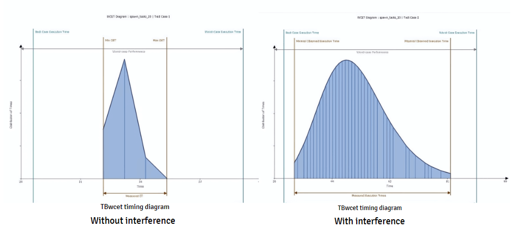
There are further complications in the case of multicore processors. The use of additional cores results in resources being shared between them. Time-related delays occur as users wait for access.

These interference channels cause the execution-time distribution to spread. Instead of a tight peak, the distribution of execution times becomes wide with a long tail.
This page presents a practical, compliant approach to addressing this problem. It involves the optimisation of system configuration by means of interference research through measured execution times using the TBrun component of the LDRA tool suite supported by the optional TBwcet module.
The LDRA tool suite is TUV certified for security- and safety-critical development, including projects developed in accordance with IEC 61508.
Where proof of fitness-for-purpose within a specified tool chain is required, the LDRA Tool Qualification Support Packs (TQSPs) contain the test cases to demonstrate both the structural coverage analysis and programming rules checking capabilities of the tool suite itself. In addition, associated documentation for the development and verification of the product is provided, including plans, procedures, and expected results.
Email: info@ldra.com
EMEA: +44 (0)151 649 9300
USA: +1 (855) 855 5372
INDIA: +91 80 4080 8707