
In the realm of rail and Guided Transportation System (GTS) software development, ever more rigorous process standards raise concerns about increased development time and cost. This challenge is further intensified by the growing complexity of modern rail systems, the integration of advanced safety and automation technologies, and the cybersecurity risks associated with interconnected systems. Even without a catastrophic failure, no developer wants to be responsible for a costly operational disruption due to a software error.
For nearly half a century, LDRA has been supporting critical software development across industries, including Rail and other GTS applications. Our expertise has contributed to shaping the standards that define best practices and ensure safety and reliability in these sectors. Our tools streamline compliance by automating adherence to industry standards, and our consultancy services provide essential guidance to both newcomers and experienced players aiming to optimize their processes.
RAMS (Reliability, Availability, Maintainability, and Safety) is a structured methodology used to ensure the dependability and safety of systems, particularly in the railway industry. For example, a train control system must meet overall RAMS objectives, such as minimizing downtime (availability), reducing maintenance intervals (maintainability), ensuring long-term reliability, and preventing unsafe conditions (safety).
Functional safety is a critical subset of RAMS. It is concerned with the management of the level of risk in a piece of equipment or a system. Functional safety development processes aim to identify potentially harmful conditions and to identify corrective actions to avoid or reduce the impact of an incident such that the response is proportionate to the risk. In practice, functional safety relies on active systems that can respond to a potentially dangerous situation.
In the context of the previous example control system, functional safety ensures that if a sensor fails, the system detects the failure and takes appropriate actions (e.g., halting the train) to avoid a collision or derailment.
Each of the RAMS series of standards has an impact on the software development lifecycle – some more directly than others.
EN 50716 is subdivided into two parts:
EN 50126 is relevant to software systems, but not specifically focused upon them. It defines the four terms Reliability, Availability, Maintainability and Safety, and describes their interaction and their management. It also defines a systematic process for specifying requirements for RAMS and demonstrating that those requirements are achieved.
EN 50216-1 and EN 50216-2 are aligned with IEC 62278-1 and IEC 62278-2, respectively.
EN 50716 supersedes and amalgamates the principles previously covered by two separate standards
EN 50716 focuses specifically on software systems and their environment. It specifies procedures and technical requirements for the development of safety related programmable electronic systems for use in railway control and protection applications.
EN 50716 is relatively new and is yet to be assigned a direct IEC equivalent.
EN 50129 is relevant to software systems, but not specifically focused upon them. EN 50129 specifies the lifecycle activities which are to be completed before the acceptance stage, and the activities to be carried out after it. It is primarily concerned with the evidence to be presented for the acceptance of safety-related systems.
EN 50129 is aligned with IEC 62425.
Embedded software developers will be primarily concerned with EN 50128 with its focus on “Software for railway control and protection systems”. However, the level of effort required to complete each objective in the standard is dependent on the Safety Integrity Level (or “SIL” – not “SIL level”) of the safety functions implemented by the system. The derivation of the SIL is covered in more detail in EN 50129.
Briefly, a SIL can be assigned to any safety-related system, sub-system or component performing a safety relevant function. The process starts with the identification of potential hazardous events. Then a Tolerable Hazard Rate (THR) is assigned for each hazardous event that might occur because of a malfunction or failure of function, expressed as a probability per unit of time and considering risk reduction measures designed to reduce the rate of occurrence.
Each hazard is then associated with a functional failure of a function or set of functions, and the THR used to derive a Tolerable Function Failure Rate (TFFR). The table below shows how a SIL is derived from the TTFR.

From the specific perspective of software development, the SIL assigned to each software component has a considerable impact on its verification and validation activity and the overhead associated with it.
As for many other sectors, rail-specific cybersecurity standards are relatively recent introductions. Consequently, more generic standards are sometimes in use.
In the Rail and other GTS industry, the evolution from closed, wired isolated networks to open, interconnected networks has led to a new generation of threats. EN 50128 only dealt with cybersecurity indirectly (when such threats have implications for safety), and it provided no specific guidance on how to address them in software.
For that reason, many GTS and rail projects have specified adherence to the IEC 62443 standard, particularly IEC 62443-4-1. The IEC 62443 series is a series of multi-industry standards defining cybersecurity protection methods and techniques categorised to apply to all stakeholders including manufacturers, asset owners and suppliers. The fourth in the series, IEC 62443-4:2018, specifies the requirements for the secure development of systems used in industrial control and automation. Rail and other GTS systems can be viewed as a niche example of this general case.
EN 50716 does address cybersecurity more directly than its processor but suggests the application of a dedicated cybersecurity standard to address it in detail.
June 2021 saw the publication of CLC/TS 50701, “Railway applications – Cybersecurity”, with the second edition being published in August 2023. CLC/TS 50701 aims to ensure that bad actors cannot compromise the RAMS characteristics of railway systems. The security models, the concepts, and the risk assessment process it describes are based on or derived from IEC 62443 series standards (above), adapted to a rail-specific context. CLC/TS 50701 covers several key topics, the most relevant here being cybersecurity during a railway application software development life cycle.
There are numerous coding standards associated with automotive software development, each with its own merits. Popular coding standards associated with the C and C++ programming languages include:
Originally developed by and for the automotive industry, MISRA C & MISRA C++ are now used across the critical software sectors, including Rail and other GTS. MISRA guidelines aim to reduce the likelihood of programming errors and improve code consistency, with resulting improvements in safety, security, and reliability.
Developed by the CERT Division at the Software Engineering Institute (SEI), CERT C & CERT C++ focus on security and best practices to avoid vulnerabilities and mitigate security risks.
Strictly speaking, CWE is not a coding standard at all. It is a broader catalogue of security weaknesses applicable to various languages and used to classify and describe these weaknesses. However, the nature of many of the weaknesses it lists is such that tools like the LDRA tool suite can find them in source code. Different types of tools are available that can find listed weaknesses pertinent to operational systems.
Additionally, organizations may choose to define their own standard, adopt multiple of these predefined standards, or tailor them to suit their specific needs.
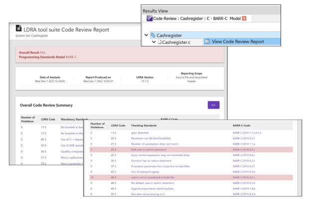
LDRA’s development tools help to alleviate the overhead faced by development teams looking to comply with automotive software standards, and with the traceability of requirements to the design and verification of code.


Email: info@ldra.com
EMEA: +44 (0)151 649 9300
USA: +1 (855) 855 5372
INDIA: +91 80 4080 8707